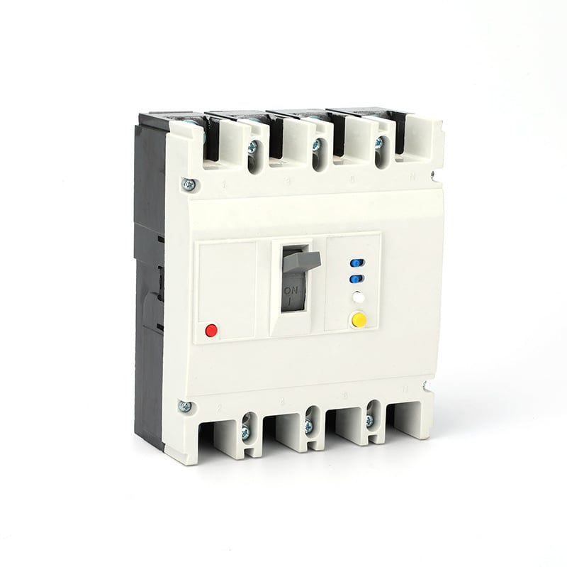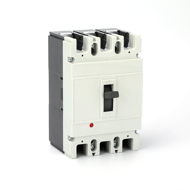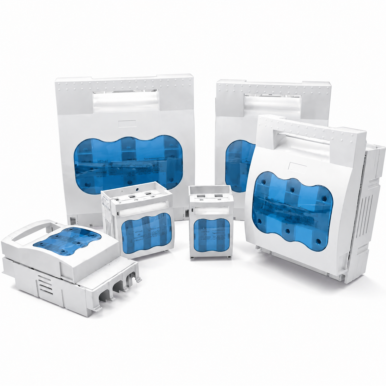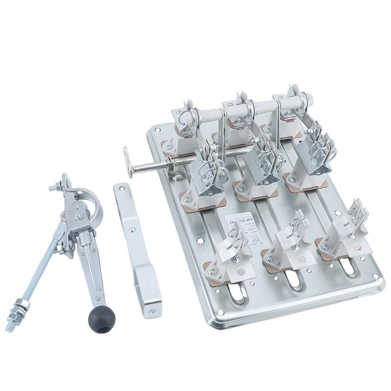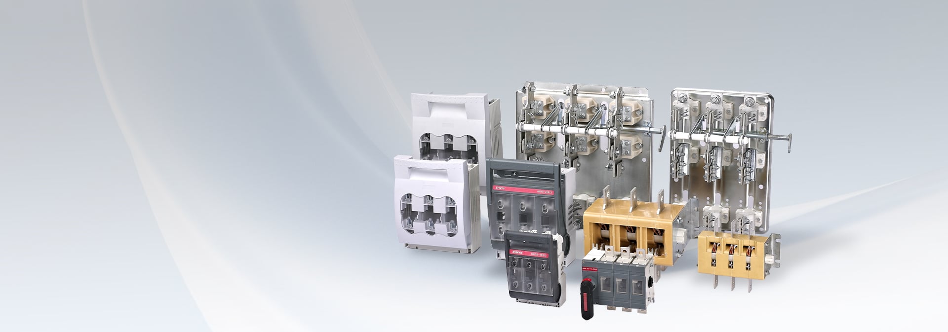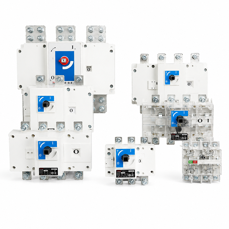
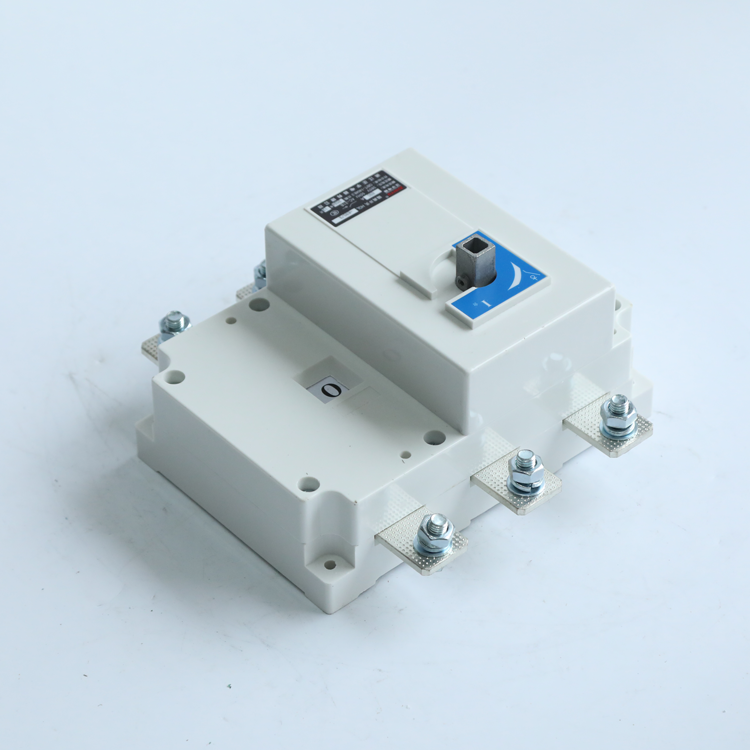
HGL series load isolation switch mainly suitable for AC 50Hz,rated voltage to 660V.DC rated voltage up to 440V,rated current up to 3150A,The switch is used in the infrequent making and breaking circuit.
Application Scenarios
The HGL Series Load Isolation Switch is designed for switching, isolating and controlling electrical circuits in low-voltage power distribution systems. With reliable isolation performance and high operational safety, it is widely used in industrial, commercial and infrastructure applications.
Power Distribution Systems
The switch is commonly used as a main switch, feeder switch or isolation switch in low-voltage distribution cabinets and switchboards. It provides safe disconnection of power sources during maintenance and servicing operations.
Industrial Facilities
Suitable for factories, manufacturing plants, processing equipment and industrial automation systems where reliable circuit isolation and load switching are required.
Commercial Buildings
Widely applied in office buildings, shopping malls, hotels, hospitals and other commercial facilities to ensure safe operation and maintenance of electrical distribution systems.
Power Generation and Energy Systems
Used in substations, generator sets, photovoltaic systems, energy storage systems and backup power systems for circuit isolation and power transfer applications.
Motor Control Systems
Installed in motor control centers (MCC), control panels and machinery equipment to provide safe switching and maintenance isolation functions.
Infrastructure Projects
Applicable to rail transit, telecommunications, water treatment plants, municipal engineering projects and other public infrastructure requiring dependable power control.
Normal working conditions
HGL series load isolation switch can work reliably under the folwina condition:
Height abovt sea level does not exceed 2 .000m;
Ambient temperature is not higher than +40℃ and not lower than -5'℃ ,Relative humiditly is not larger than 95%;
No explosive dangerous medium environment;
No rain and snow attack environment;
Note:lf the load isolation switch is expected to be used in the conditon that the ambient temperature is higher than +40'℃ or is lower than-5 ℃~-45℃,customers should inform to the manufactory.
Structural features
The HGL Series Load Isolation Switch adopts a modular design concept and advanced manufacturing technology, providing reliable switching performance, excellent insulation characteristics and flexible installation options.
Modular Structure Design
The switch features a compact modular construction, allowing flexible configuration according to different installation requirements while reducing panel space occupation.
High-Performance Insulating Housing
The housing is manufactured from glass-fiber reinforced unsaturated polyester resin, providing excellent dielectric strength, flame resistance, mechanical durability and environmental resistance.
Quick-Make Quick-Break Mechanism
The operating mechanism utilizes an energy-storage spring acceleration system that enables independent quick opening and quick closing actions. The switching speed is not affected by handle operation speed, ensuring reliable interruption performance and improved electrical life.
Double-Break Contact Structure
The double-break contact design significantly improves breaking capability, reduces arc duration and enhances operational safety under load switching conditions.
Flexible Operation Modes
The switch supports multiple operating methods, including:
Front operation
Side operation
Inside-panel operation
Outside-panel operation
This flexibility allows easy integration into various switchgear and distribution cabinet designs.
Auxiliary Function Expansion
Optional auxiliary contacts can be installed for status indication, interlocking control and remote monitoring applications.
Reliable Mechanical Performance
The robust operating mechanism provides stable switching performance, strong anti-vibration capability and long service life under demanding operating conditions.
Product Model and Its Meaning Technical Parameters
Conventional thermal current Ith(A)
63A
100A
160A
Rated currentin(A)
40
63
80
100
125
160
Rated impulse withstand voltage Ui(V)
750
750
750
750
750
750
Dielectric strength(V)
5000
5000
5000
5000
5000
5000
Rated Working currentle(A)
380V
AC-21
40
63
80
100
125
160
AC-22
40
63
80
100
125
160
AC-23
40
63
80
100
125
160
660V
AC-21
40
50
80
80
125
160
AC-22
32
32
50
50
125
160
AC-23
25
25
40
40
80
80
220V
DC-21
40
63
80
100
125
160
DC-22
40
63
80
80
125
160
DC-23
40
63
63
63
125
125
440V
DC-21
100
125
DC-22
100
125
DC-23
100
125
Motor power P(Kw)
380V
18.5
25
40
40
63
80
660V
22
22
33
33
75
75
Rated short-time withstand current lcw(kARms)0.1s/1.0s
10-5
10-5
10-5
10-5
20-10
20-10
Rated breaking capability lcn(Arms)Ac23380V
320
504
640
800
1000
1000
Rated making capability lcm(ARms)AC23380V
400
630
800
1000
1250
1250
Rated short-current making capability lcm(KA peak value)
7.5
7.5
10
10
12
12
Mechanical durability(number of cyclic operation)
10000
10000
10000
10000
10000
10000
Electric durability(number of cyclic operation) Ue=660V.Rated current le
Scope of Application
Application Scenarios
Normal working conditions
Structural features
Product Model and Its Meaning
Technical Parameters
Conventional thermal current Ith(A)
63A
100A
160A
Rated currentin(A)
40
63
80
100
125
160
Rated impulse withstand voltage Ui(V)
750
750
750
750
750
750
Dielectric strength(V)
5000
5000
5000
5000
5000
5000
Rated Working
currentle(A)
380V
AC-21
40
63
80
100
125
160
AC-22
40
63
80
100
125
160
AC-23
40
63
80
100
125
160
660V
AC-21
40
50
80
80
125
160
AC-22
32
32
50
50
125
160
AC-23
25
25
40
40
80
80
220V
DC-21
40
63
80
100
125
160
DC-22
40
63
80
80
125
160
DC-23
40
63
63
63
125
125
440V
DC-21
100
125
DC-22
100
125
DC-23
100
125
Motor power P(Kw)
380V
18.5
25
40
40
63
80
660V
22
22
33
33
75
75
Rated short-time withstand current lcw(kARms)0.1s/1.0s
10-5
10-5
10-5
10-5
20-10
20-10
Rated breaking capability lcn(Arms)Ac23380V
320
504
640
800
1000
1000
Rated making capability lcm(ARms)AC23380V
400
630
800
1000
1250
1250
Rated short-current making capability lcm(KA peak value)
7.5
7.5
10
10
12
12
Mechanical durability(number of cyclic operation)
10000
10000
10000
10000
10000
10000
Electric durability(number of cyclic operation)
Ue=660V.Rated current le
COSφ=0.95 AC21
1700
1700
1700
1700
1500
1500
COSφ=0.65 AC22
100
100
100
100
1000
1000
COSφ=0.35 AC23
500
500
500
500
500
500
Moment of operation(Nm)
1.2
1.2
1.2
1.2
6.5
6.5
250A
630A
1600A
3150A
200
250
315
400
500
630
1000
1250
1600
2000
2500
3150
750
750
1000
1000
1000
1000
1000
1000
1000
1000
1000
1000
5000
5000
8000
8000
8000
8000
10000
10000
10000
10000
10000
10000
8
8
12
12
12
12
12
12
12
12
12
12
200
250
315
400
500
630
1000
1250
1600
2000
2500
3150
200
250
315
400
500
630
1000
1250
1600
2000
2000
3150
200
250
315
340
425
536
200
250
315
400
400
500
1000
1000
1600
2000
2500
2500
160
160
315
315
315
315
800
800
800
1000
1000
1000
100
125
125
125
125
125
200
250
315
400
500
630
1000
1250
1600
2000
2500
2500
200
250
315
400
400
500
1000
1250
1250
1600
1600
1600
160
200
160
200
315
400
400
500
1000
1250
1250
2000
2000
2000
160
200
315
400
400
500
1000
1250
1250
1250
1250
1250
160
200
315
400
400
500
1000
1000
1000
100
132
160
220
280
315
560
560
560
710
710
710
90
110
185
185
185
185
475
475
475
750
750
750
30-12
30-12
45/20
45/20
50/25
50/25
90/50
90/50
90/50
90/50
90/50
90/50
1600
1600
2500
3200
3200
3200
2000
2000
3150
4000
4000
4000
17
17
30
30
40
40
10000
10000
5500
5500
5500
5500
4000
4000
3000
1500
1500
750
750
750
750
600
600
450
2500
2500
2500
1000
1000
500
500
500
500
400
400
300
500
500
250
250
250
250
200
200
150
10
10
14.5
14.5
14.5
14.5
37
37
60
60
60
60
External appearance and installation dimensions
Specification
External dimension and installation dimension
In
A
A1
B
C
D
E
φL
J
K
N
P
R
S
T
U
φ×
Y
125A/3
141
50
135.5
115
27
70
5.5
120
65
85
36
20
235
3
85
9
21
125A/4
170
50
135.5
115
27
70
5.5
150
65
85
36
20
235
3
85
9
21
160A/3
141
50
135.5
115
27
70
5.5
120
65
85
36
20
235
3
85
9
21
160A/4
170
50
135.5
115
27
70
5.5
150
65
85
36
20
235
3
85
9
21
200A/3
180.5
60
170.5
132
35
85
5.5
160
90
115
50
25
290
3
110
11
25
200A/4
230.5
60
170.5
132
35
85
5.5
210
90
115
50
25
290
3
110
11
25
250A/3
180.5
60
170.5
132
35
85
5.5
160
90
115
50
25
290
3
110
11
25
250A/4
230.5
60
170.5
132
35
85
5.5
210
90
115
50
25
290
3
110
11
25
315A/3
230
85
240
174
50
118
7
210
140
145
65
30
400
5
160
11
35
315A/4
290
85
240
174
50
118
7
270
140
145
65
30
400
5
160
11
35
400A/3
230
85
240
174
50
118
7
210
140
145
65
30
400
5
160
11
35
400A/4
290
85
240
174
50
118
7
270
140
145
65
30
400
5
160
11
35
500A/3
230
85
260
175
50
118
7
210
140
145
65
40
400
5
160
13
35
500A/4
290
85
260
175
50
118
7
270
140
145
65
40
400
5
160
13
35
630A/3
230
85
260
175
50
118
7
210
140
145
65
40
400
5
160
13
35
630A/4
290
85
260
175
50
118
7
270
140
145
65
40
400
5
160
13
35